Hydraulic Symbol
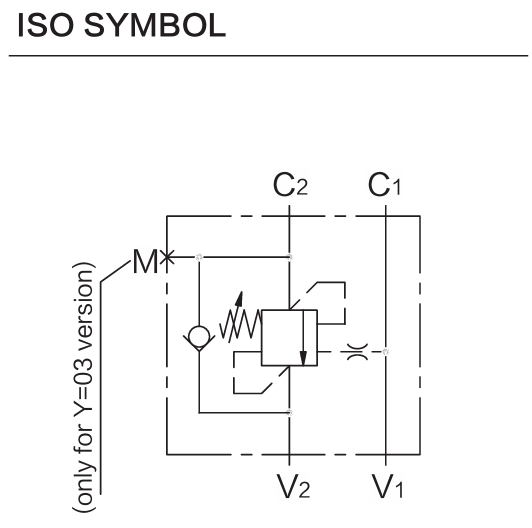
Description
Valve block structure, pipe installation.
Operation
When pressure at V2 rises above the spring bias pressure, the check seat is pushed away from the piston and flow is allowed from V2 to C2. When load pressure at C2 rises above the pressure setting, the direct-operated, differential-area relief function is activated and flow is relieved from C2 to V2. With pilot pressure at V1-C1, the pressure setting is reduced in proportion to the stated ratio of the valve, until opening and allowing flow from C2 to V2. The spring chamber is drained to V2, and any back-pressure at V2 is additive to the pressure setting in functions. Note: ports identified with M are not protected with calibrated orifice but are in direct connection with pressure channels.
Technical Data
| Operating Pressure | Max. Operating Pressure: 350 bar; maximum setting = 350 bar; maximum recommended load pressure at maximum setting = 270 bar |
|---|---|
| Flow | See Performance Chart |
| Internal Leakage | 15 drops/min max. to 80% of nominal setting |
| Temperature | -40°C to 120°C with standard Buna seals |
Performance Curve
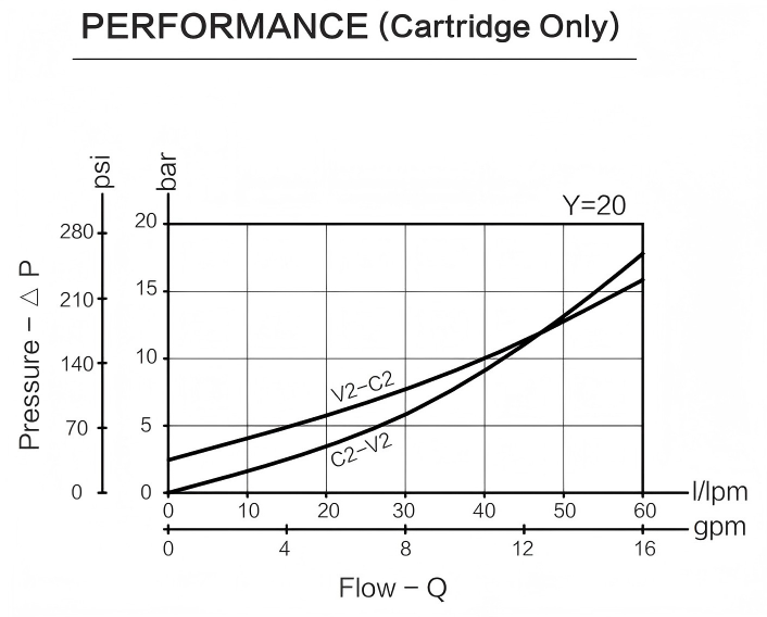
Flow performance should be reviewed together with pressure drop and working conditions.
Dimensions
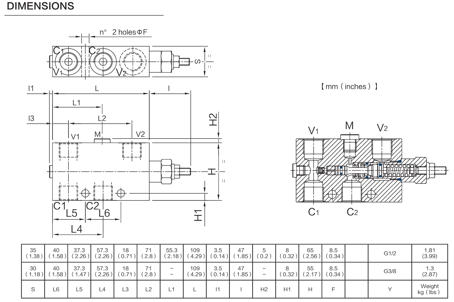
Dimension drawing is provided for installation and cavity review.
Materials & Ordering Options
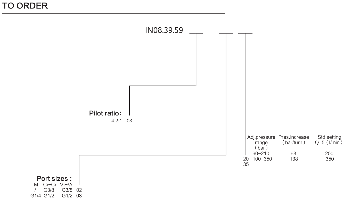
Materials, seal options, coil voltage, connector types and ordering options are shown for product selection review.
File Download
Useful RFQ Information
Please provide the following information for faster matching:
- Original part number, current supplier reference or product photos
- Voltage, connector type and coil dimensions, if applicable
- Cavity, pressure, flow and seal requirements, if applicable
- Equipment application and expected quantity
- For custom manufacturing or special matching, drawings, samples or detailed photos are recommended for accurate review.
Thank you for providing the required information. This will help us review and match the correct product more efficiently.
Request a Quote